This post is about the wiring of the OBD2 port from a 2004 “Restyle” 6AT Lexus LS430. The engine will be swapped into another car but I want to keep the port for diagnostics and flashing.
In this post I will not go into the details how to power up the ECU itself.
Goals
- Compatible with generic OBD2 scan tools
- Compatible with Toyota Techstream via Tactrix Openport 2.0
- Reading and flashing with PCMFlasher and Tactrix Openport 2.0
- Modular in order to extend the CAN bus on the car
- 3UZ Ecu Harness and OBD-Port Harness are terminated with 120 Ohms, every other node goes in between these two
- CAN Bus provides ground and 12V from a single source starting at the ECU
- Gateway ECU is removed
Research
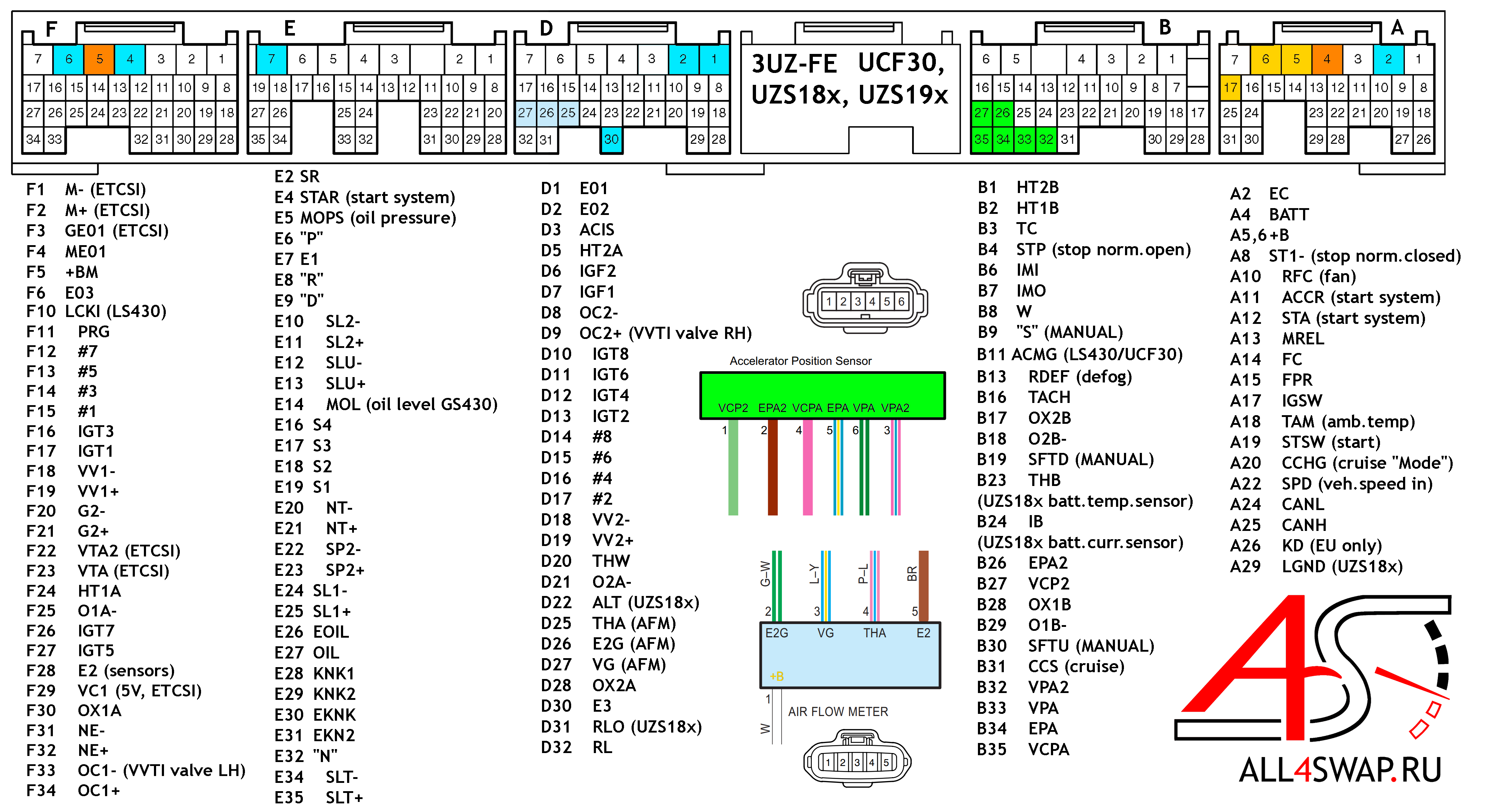
A good starting point for this wiring is the diagram provided publicly by all4swap.ru. Notable for the OBD2 port wiring are the following pins.
- A4 BATT: This is the permanent 12V battery connection to the ECU. I will feed this into the CAN bus as a power source. This Pin will also be fused for 7.5A before entering the ECU.
- A24 CANL and A25 CANH: These pins are the CAN lines of the ECU. From 2004ish on Toyota and Lexus started using these lines instead of the older SIL line which is not available anymore without the additional gateway ECU of the LS430.
- Signal Ground: The signal ground is used on the OBD2-Port and is different to chassis ground. I will however not use the ECU’s signal ground in order to keep the plug A self sustaining and separated from the other plugs. Both grounds will be chassis in my case. More info on this topic at mechanics.stackexchange.com
- B3 TC: This pin is used for timing checks on the car. It also enables the “diagnostics mode” on the ECU when grounded. In this mode I was able to connect via Techstream to the ECU. In order to keep A separate from B I will put a switch or connector on the B harness that grounds or ungrounds B3.
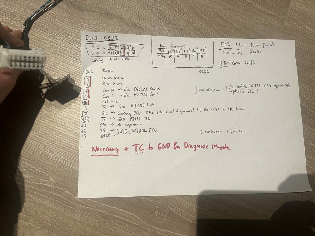
The OBD2 connector has 16 pins and it is a Toyota DLC3 connector. For our goals only 5 connections are actually necessary.
- 4 and 5: These are the ground pins and are connected to the chassis ground
- 6 Can High: This one gets connected to A25 CANH on Ecu
- 14 Can Low: This one gets connected to A24 CANL on Ecu
- 16 +12V: This one gets connected with A4 incoming from the battery (remember a fitting fuse before the ECU!)
Here are some additional notes I have on this topic.
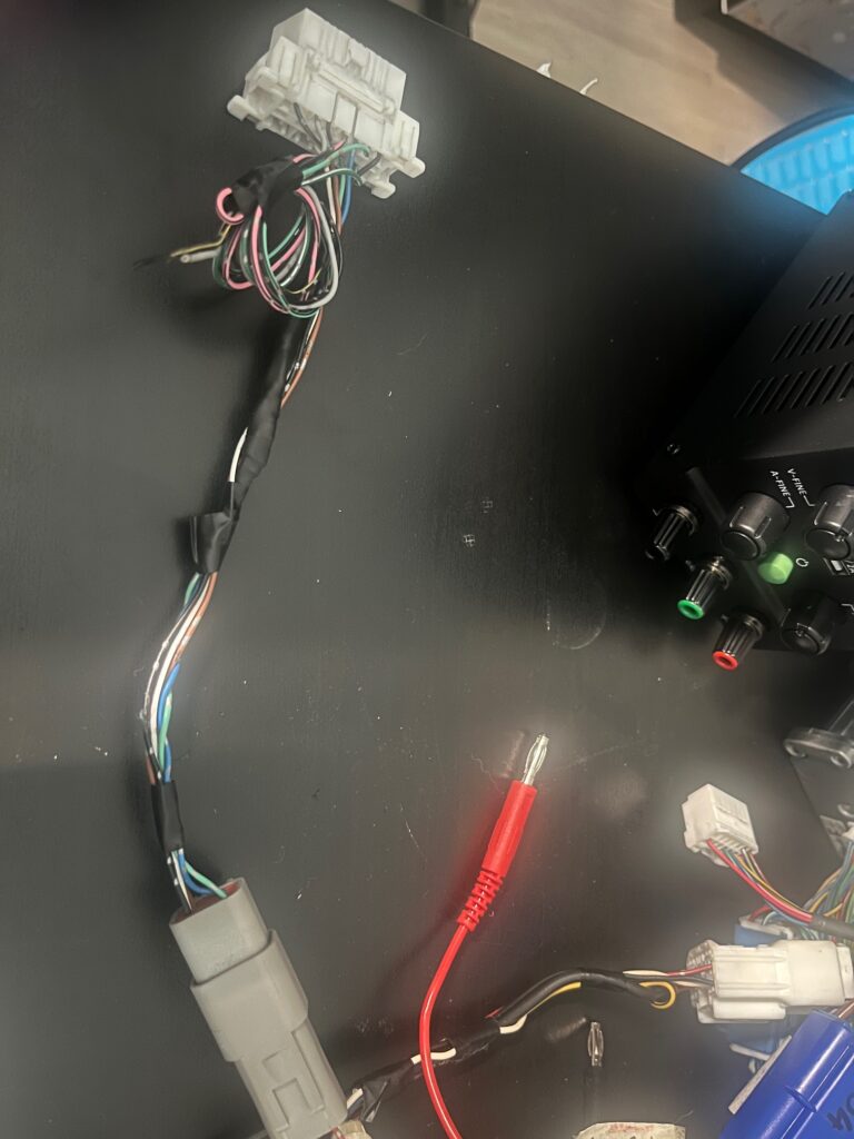
Harness
The resulting harness looks like this. From ECU plug A I branched off A24, A25 into the left branch of the harness. The right branch provides all grounds and 12V to plug A. From the right branch I connected battery 12V and a ground to the left branch.
In the left branch there is 120 Ohm terminating resistor between CanH and CanL. This means the ECU is a terminating device in the whole CAN bus.
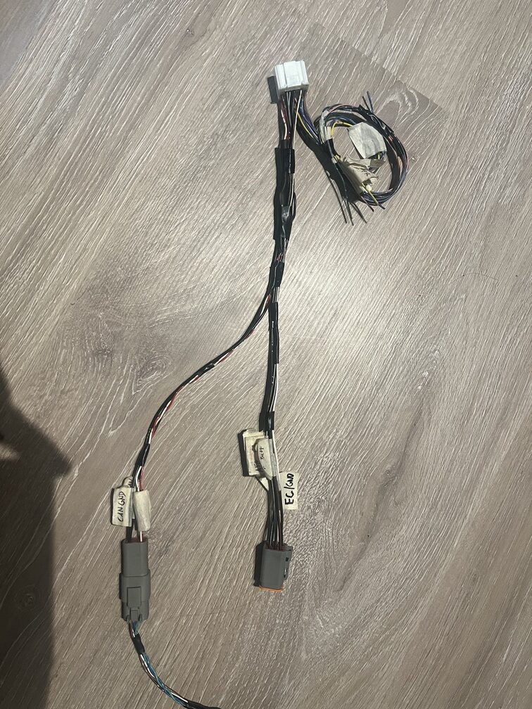
The plug on the left branch therefore results in CanH, CanL, 12V from battery and Gnd.
In my case I used Deutsch DT connectors and the pinout is:
- Pin 1 is CanL
- Pin 2 is CanH
- Pin 3 is +12V
- Pin 4 is Ground
From the DT connector it goes straight into the OBD connector as described in the research chapter.
CanH and CanL are again connected with a 120 Ohm terminating resistor making the OBD port the other end of the CAN bus. All the other CAN devices will go in between of these two.
Verification
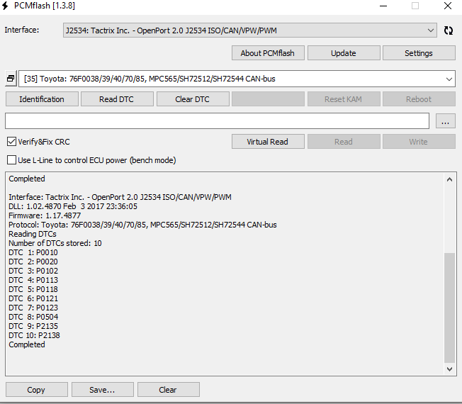
I connected the setup on a table with a powered ECU to Techstream and am able to read data. I did the reading with Openport clone since the original Tactrix adapter is still in the mail.
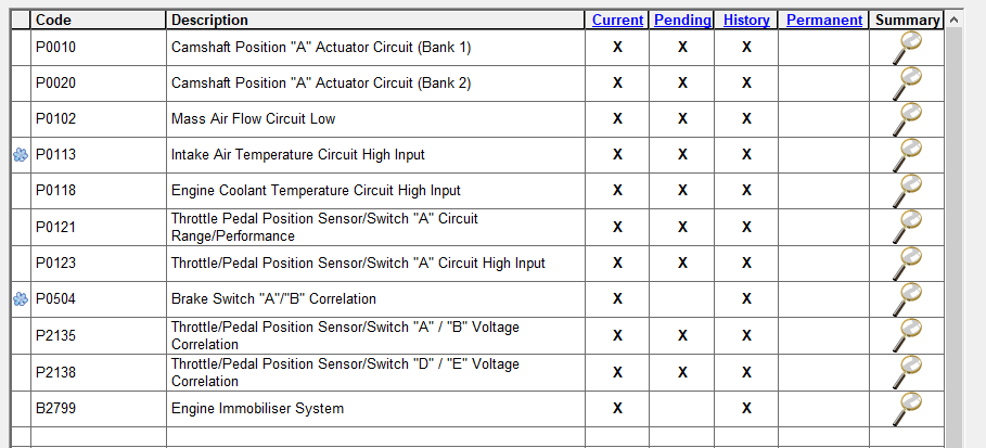
After the original Tactrix device arrived I was able to use PCMFlasher to read and write the ECUs .bin file. Which in the mean time was modified with Toyolex4 to remove the immobilizer (See missing code 2799).
Both connections were made in the diagnostics mode.