In this post I will continue to describe the planned CAN-Bus Topology

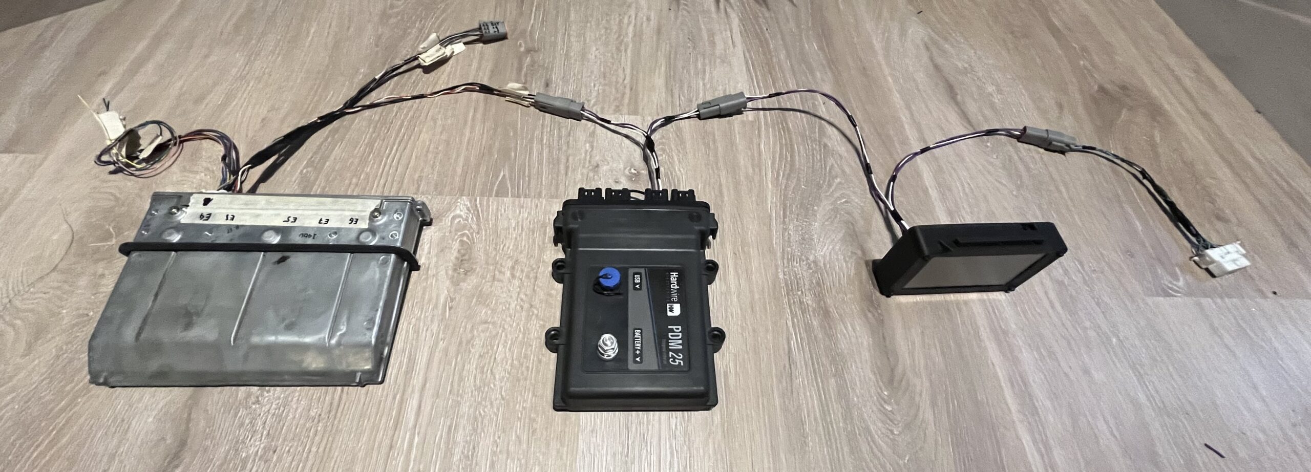
This is the current layout of the CAN-Bus. From left to right:
- 3UZ ECU: One plug goes into the CAN-Bus and provides +12V to the bus. It is taken from the BAT connection to the ECU. The other plug provides grounds and power to the ECU.
- Hardwire PDM: Listens on CANH and CANL. This unit does not need the ground and +12V wire from the bus.
- Self-made digital dash: This unit shows all the important data from the ECU and PDM. It also allows for touch screen controls like resetting the PDMs fuses or (planned!) resetting the DTCs of the ECU. It uses ground and +12V for its own power.
- OBD Port as described in the according wiring post.
In the current topology the CAN keypad for controlling the PDMs function is not yet visible. It will be connected similiar to the digital dash once all necessary parts for building it arrive.
I am using Deutsch DT06-4S connectors and the Pin numbers are assigned the following functions:
- Pin 1 is CANL
- Pin 2 is CANH
- Pin 3 is BAT
- Pin 4 is GND